3D-Printed Pneumatic Rocket Launcher
Independent design and development · 2025–2026 · Iterative prototyping and testing
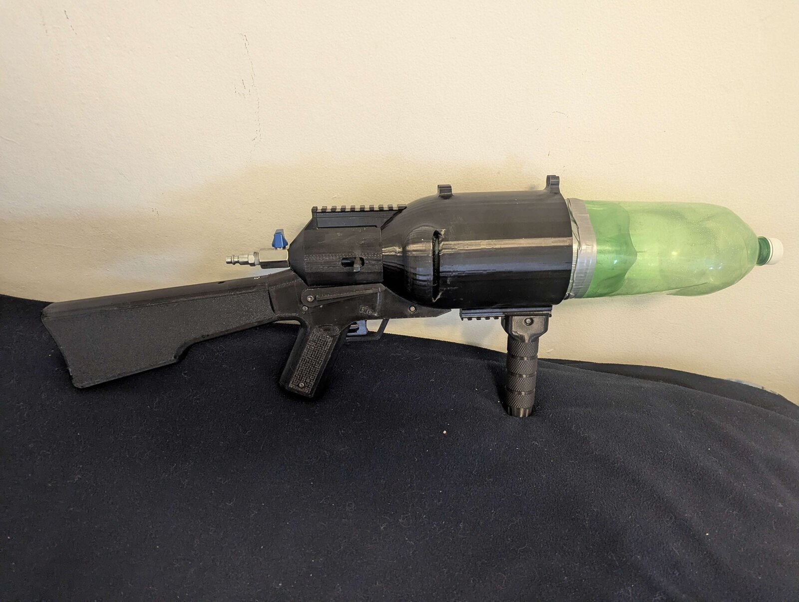
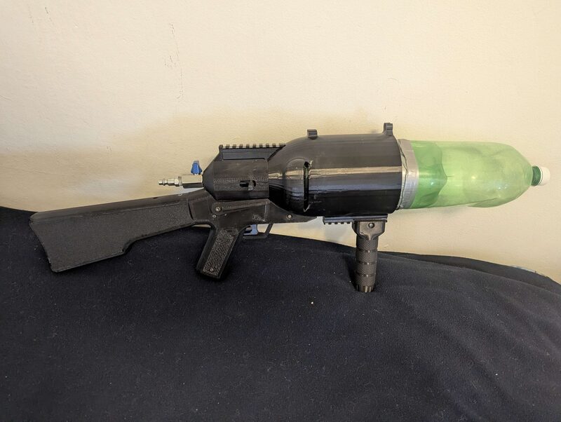
Assembled pneumatic launcher with a bottle attached, illustrating the complete mechanical system and its major functional components.
Project Overview
This independent engineering project began with the challenge of designing a practical, reusable pneumatic bottle-rocket launcher built primarily from 3D-printed components. I designed the complete mechanical system, manufactured and assembled successive prototypes, and developed an experimental testing process to find weaknesses and improve the design.
The work has given me extensive experience in mechanical design, additive manufacturing, dimensional tolerances, fluid pressure systems, materials selection, and iterative engineering. The launcher remains an active project — the current revision is a working prototype, not a finished product.
The Engineering Challenge
A pressurised bottle is a deceptively demanding thing to build a machine around. The launcher has to hold a sealed air charge against a consumer soda bottle, release it on command through a mechanical trigger, survive the recoil of that release, and do it all repeatedly — using parts made on a desktop 3D printer, where layer adhesion, print tolerances, and material behaviour all work against you.
The design problems that drove most of the development work were:
- Creating reliable seals in 3D-printed assemblies.
- Designing accurately fitting threaded connections.
- Developing mechanical triggering and release components.
- Managing dimensional tolerances between printed parts.
- Improving durability and structural rigidity.
- Balancing component strength against printability, assembly complexity, and material consumption.
- Incorporating feedback from repeated physical testing.
Design and Iteration
The launcher has gone through multiple major revisions, each one informed by what physically broke or leaked on the previous prototype. Rather than treating a completed CAD model as the final product, I kept returning to the design after finding weaknesses in hardware.
Changes across generations have included adjustments to thread dimensions, trigger geometry, component reinforcement, mounting interfaces, material selection, and assembly hardware. Several of those changes came directly out of failures: enlarging the charging-handle clearance after repeated premature fires, tightening the Schrader thread after an immersion test showed it was finger-loose, and moving away from PLA after a prototype softened and warped in a hot car.
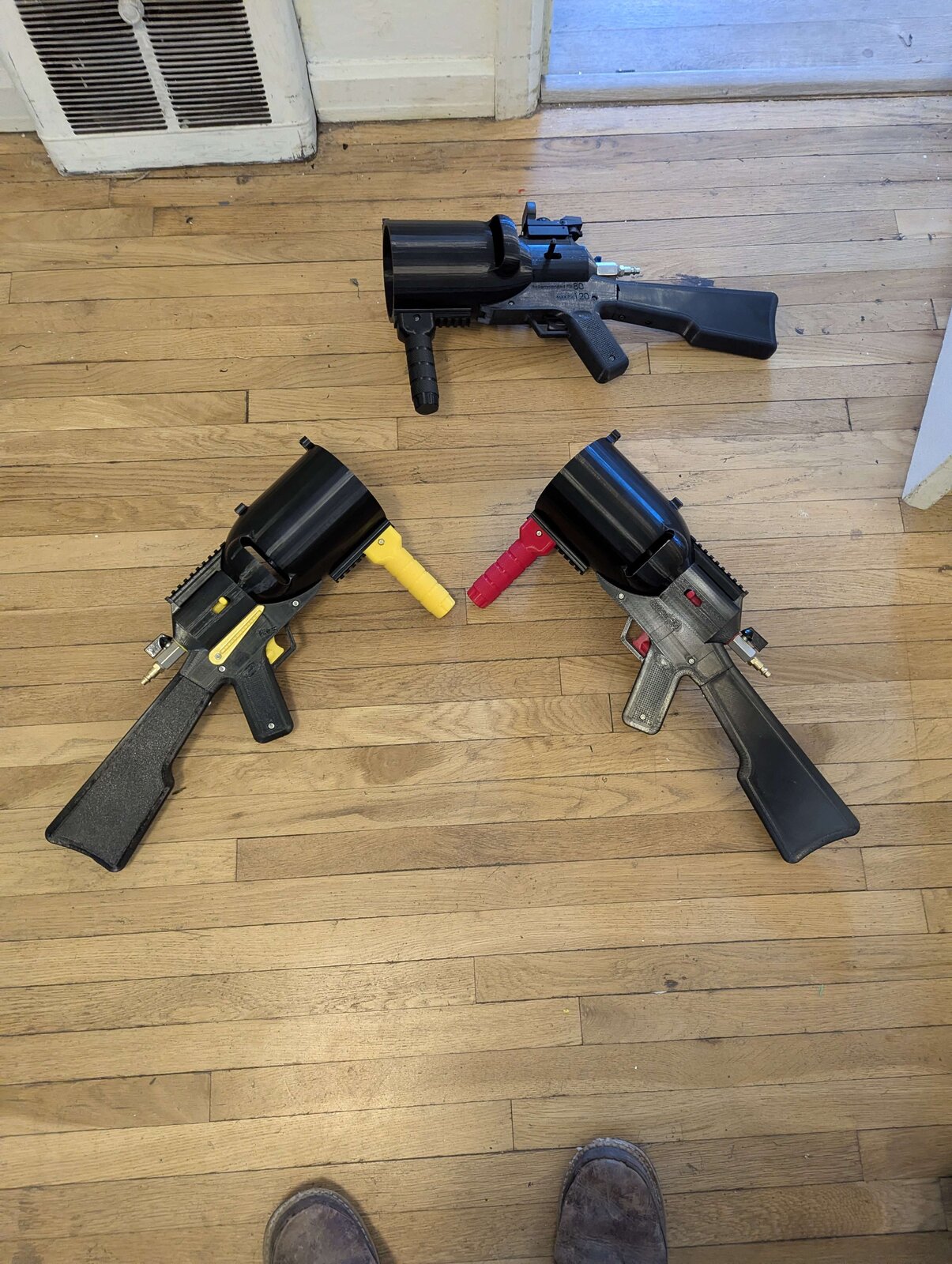
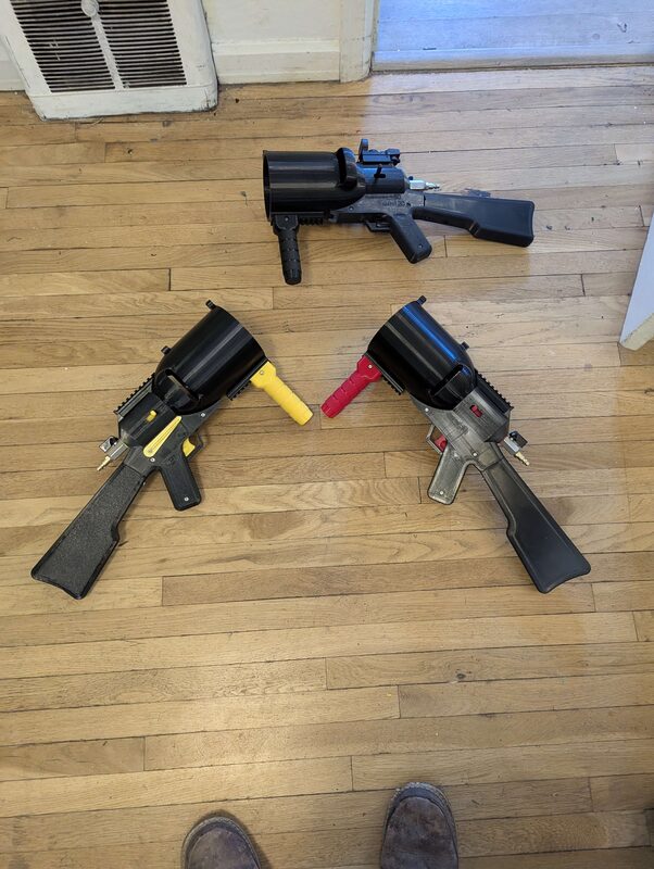
Multiple printed prototypes illustrating successive design revisions and changes to the controls, housing, and assembly. Click to enlarge.
Engineering Pressurised Components
The central challenge was designing a mechanical assembly that could reliably retain pneumatic pressure while being made from additively manufactured parts. That meant paying close attention to component geometry, threaded interfaces, O-ring sealing, material behaviour, and structural loading.
Early leak testing pointed at the threaded connections and worn seals rather than the printed parts themselves, which led to dimensional refinements and revised components. Separately, thermal deformation of a PLA prototype during testing demonstrated the limits of that material for this application and motivated a move to more temperature-resistant printing materials.
Experimental Testing and Validation
I ran and documented several distinct testing programs to evaluate the design. These were shop-built experiments with the instrumentation I had on hand, so their conclusions are indicative rather than certified — but they produced concrete evidence that drove subsequent design changes.
Fatigue and repeated operation
Prototype V3.1 was fired repeatedly at different pressures, with and without water, to observe mechanical behaviour, release reliability, and the effect of repeated loading on the mechanism. Of eleven runs the only failure was a premature fire, which I traced to the charging handle being knocked while the launcher sat on the ground.
Leak testing
Pressure-retention measurements and water-immersion testing were used to locate leakage. The immersion test was what separated losses inside the launcher from losses in the external inflation equipment — most of the measured pressure drop turned out to be the bike pump, not the launcher.
Destructive pressure testing
A destructive test on the high-pressure components investigated failure behaviour. The test bottle failed somewhere between roughly 140 and 150 psi, and the wreckage gave evidence about deformation, fracture location, and secondary damage to the mechanical parts. It characterises one failure event on one setup; it is not a safety certification.
Component redundancy testing
Prototype V3.3 was pressurised under eight different clamp configurations to see what happens when clamps are missing. The results showed that clamp distribution matters more than count: configurations with clamps on both sides of the centreline held high pressures, while clamps grouped on one side failed at a fraction of that.
Test Documentation
The detail behind each test, including the raw results and photographs, is collapsed below.
V3.1 — Fatigue and repeated-operation test
Eleven launches of prototype V3.1 at varying pressures, with and without water in the bottle.
| Test | Pressure (psi) | Water | Result |
|---|---|---|---|
| 1–6 | 80 | Yes | Success |
| 7–9 | 80 | No | Success |
| 10 | 70 | No | Failure — premature fire |
| 11 | 110 | No | Success |
Discussion. The single failure was a premature fire, most likely caused by the charging handle being bumped while the launcher was on the ground, loosening the trigger enough to release. Flight behaviour was a separate problem: with water in a horizontally mounted bottle the rocket was unbalanced and nosed down hard, and air could escape past the water rather than expelling it. Air-only launches flew better, and adding a launch rail with zip-tie loops improved flight path further.
After this test the PLA launcher was left in a hot car and softened and warped, rendering the bell body, charging handle, and side plates unusable. That result drove the switch to a more heat-resistant printing material.
V3.2 — Destructive pressure test
Method. Only the high-pressure components were tested: the launch tube, clamps, O-rings, trigger, Schrader valve, and a two-litre soda bottle. The bottle was filled roughly 95% with water to reduce the stored energy of an explosion, then pressurised from an air compressor in stages. As pressures rose I moved behind a cooler and placed a kiddie pool over the bottle.
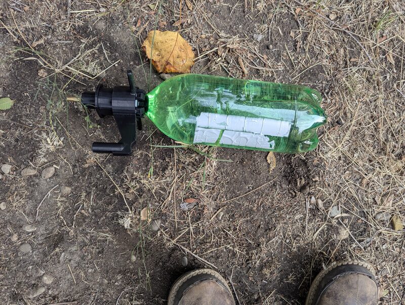
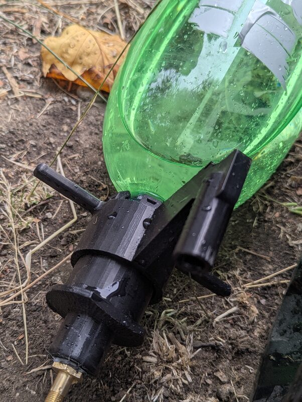
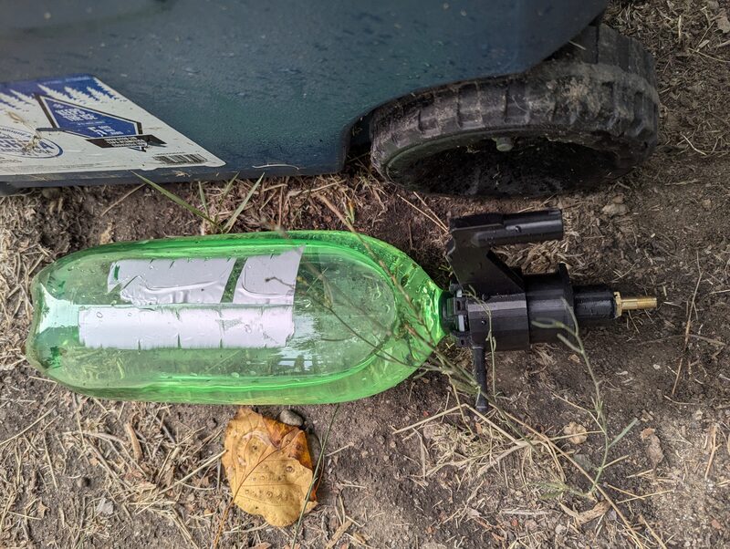
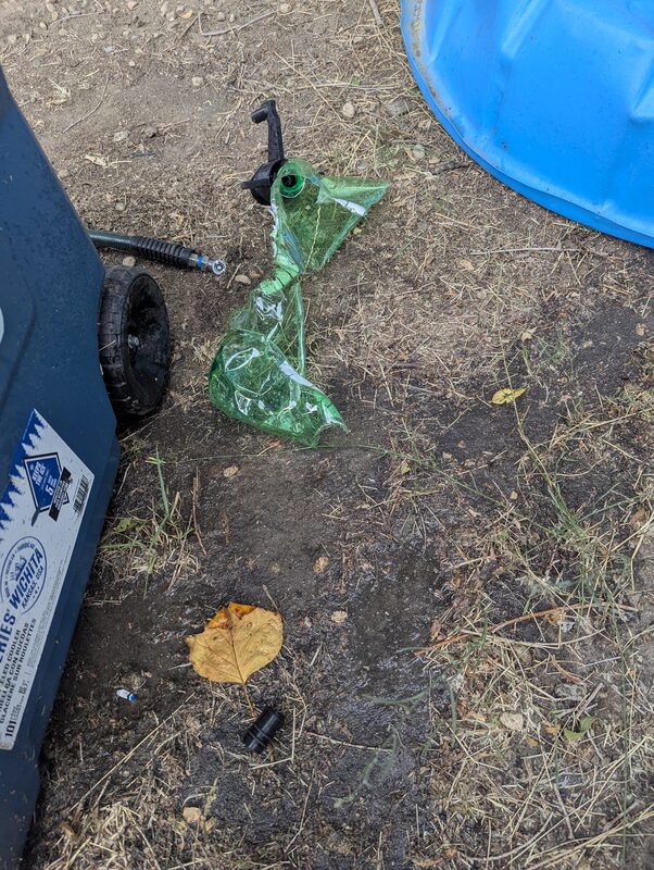
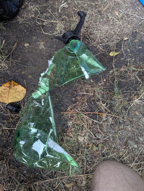
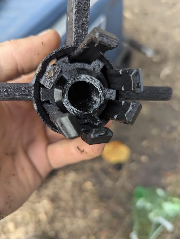
Results. Pressure was raised in roughly 10 psi increments from 100 psi. Nothing notable happened until 120 psi, where the bottle began to swell slightly. At 133 psi the swelling was more pronounced, filling took noticeably longer, and stress cracks appeared near the neck. At 140 psi the bottle swelled considerably and airflow never fully stopped. The system failed while filling from 140 to 150 psi: the bottle split and the internal mechanism broke.
Discussion. Without a dedicated pressure or strain gauge this is an ad-hoc test, and I've tried to be careful about what it does and does not show. The bottle split at the side wall rather than at the neck cracks I expected, which matches high-speed footage of similar tests published online. The printed-part failures were all one-sided, with only one clamp broken, pointing to an asymmetric burst in the air bubble above the water line — so my assessment is that the bottle is the failure mode, and the launch tube and clamp damage are artefacts of the test setup that could likely have withstood more pressure.
Conclusion. The bottle split at somewhere between 140 and 150 psi and the blast broke the launch tube and a clamp. This informs the pressure rating and safety-factor choices for the design. It is a single destructive data point on one bottle and one assembly, not a demonstration that any particular operating pressure is safe.
V3.2 — Leak test
Method. The first test pumped the system to 100 psi and watched the bike-pump gauge. The immersion tests submerged the launch tube, trigger, clamps, and a pressurised bottle in a cooler full of water.
Results. Pressure fell from 100 psi to 80 psi in 1 minute 19 seconds as measured at the pump — but the immersion test showed almost all of that loss was through the pump itself. With the pump detached, most leakage stopped: no leaks in the threads, very little through the part, and small leaks through the O-rings when the assembly was impacted. The O-rings in use were old and damaged. A second immersion test did find leakage at the Schrader valve threads, which were finger-loose.
Conclusion. Encouraging overall, with two clear actions: decrease the thread size and replace the O-rings.
V3.2 — Playtesting
Results. The launcher fired prematurely a few times, caused by the charging handle not travelling far enough forward. I fixed it by enlarging the holes by hand and then carried the change back into CAD.
Stress testing at 130 psi caused the bottle to swell and jam in the bell; we bled air out through the Schrader valve until it came free and fired. The press-fit ring of the bell failed during this, though the lower bolt held it in place — the bell body was never designed to take the load of a swelling bottle. A later firing with only the front bolt installed, at a reasonable pressure, forced the main body apart and cracked the Picatinny rail, body, and stock.
Failures and fixes identified:
- Over-pressured bottle jamming in the bell → introduce a pressure rating and consider a reinforcing sleeve to limit bottle swelling.
- Bell body coming off → use the production press-fit tolerance; don't over-pressurise.
- Main body cracking → install all bolts.
- Picatinny rail cracking → stronger slicer settings; don't over-pressurise.
- Premature firing → enlarge the charging-handle hole.
V3.3 — Clamp redundancy test
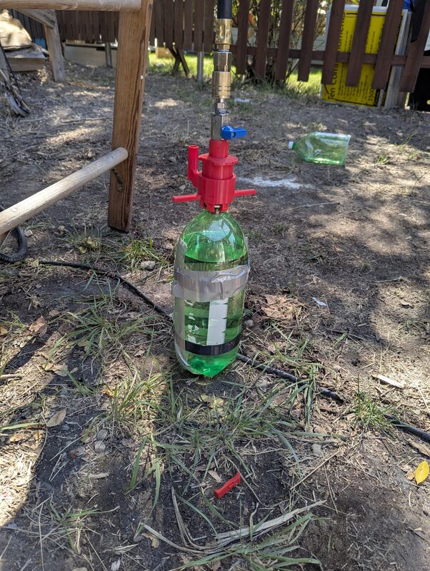
Method. With a water-filled bottle and the launch tube, clamps, and trigger attached, I opened the compressor valve at 0 psi and gradually raised the regulator, recording the result for each clamp configuration. Only one O-ring was available, and the clamps were a mix of original and reverse-engineered versions.
| Test | Max pressure reached (psi) | Result |
|---|---|---|
| 1 | 120 | Success |
| 2 | 120 | Success |
| 3 | 110 ± 5 | Failure (no damage to setup or bottle) |
| 4 | 20 ± 5 | Failure — launch ring would not engage |
| 5 | 15 ± 2 | Failure |
| 6 | 125 ± 2 | Failure |
| 7 | 135 | Success — compressor hit its maximum |
| 8 | 135 | Success — compressor hit its maximum |
Discussion. The pattern is about geometry, not quantity. Three evenly spaced clamps reached 110 psi, but three clamps grouped on one side of the centreline managed only 15 psi. With four or more clamps it becomes inevitable that some sit on each side, and those configurations reached 125 and 135 psi.
Tests 7 and 8 never actually failed — the compressor topped out at 135 psi — so their true limit is unknown. Taken with the destructive test, where six clamps survived past the compressor's maximum, it seems likely that five clamps, or four in the test 7 arrangement, can hold more pressure than an unreinforced bottle will.
High-pressure-air shot capacity analysis
A first-order analysis of how many launches a compressed-air (HPA) tank could realistically supply. Treating temperature and the gas constant as equal between the tank and the bottle, the ideal gas law makes the mass of air proportional to pV, so the number of shots is simply the ratio of available air to air consumed per shot:
n = (ptank Vtank) / (pbottle Vbottle)
| Tank | Bottle volume | 80 psi | 100 psi | 110 psi |
|---|---|---|---|---|
| 48 ci, 3000 psi | 1.1 L air | 26.8 | 21.5 | 19.5 |
| 48 ci, 3000 psi | 0.75 L water/air | 39.3 | 31.5 | 28.6 |
| 48 ci, 4500 psi | 1.1 L air | 40.2 | 32.2 | 29.3 |
| 48 ci, 4500 psi | 0.75 L water/air | 59.0 | 47.2 | 42.9 |
These are theoretical figures assuming no losses and constant temperature. A 4500 psi tank gives about 50% more shots than a 3000 psi tank at the same bottle pressure and volume, and dropping the bottle volume from 1.1 L to 0.75 L adds roughly 47%. Even the worst case — a cheap 48 ci, 3000 psi tank at 110 psi air-only — gives about 20 shots.
Engineering Lessons
- Functional prototypes reveal problems that are difficult to anticipate in CAD.
- Additive manufacturing demands careful attention to material properties and geometric tolerances.
- Repeatable experiments are what separate assumptions from observed performance.
- A failure analysis is often more valuable than a successful test when deciding what to improve.
- Good product development means repeatedly revisiting earlier design decisions.
Taken together, the project is an independent progression through mechanical design, fabrication, assembly, experimentation, and redesign — and it is still going.
Gallery